CI3
3 kg payload · 600 mm working radius
Collaborative robots
Six-axis robot arms for machine tending, handling, assembly and inspection, with a shared controller and Kikobot Studio software platform.
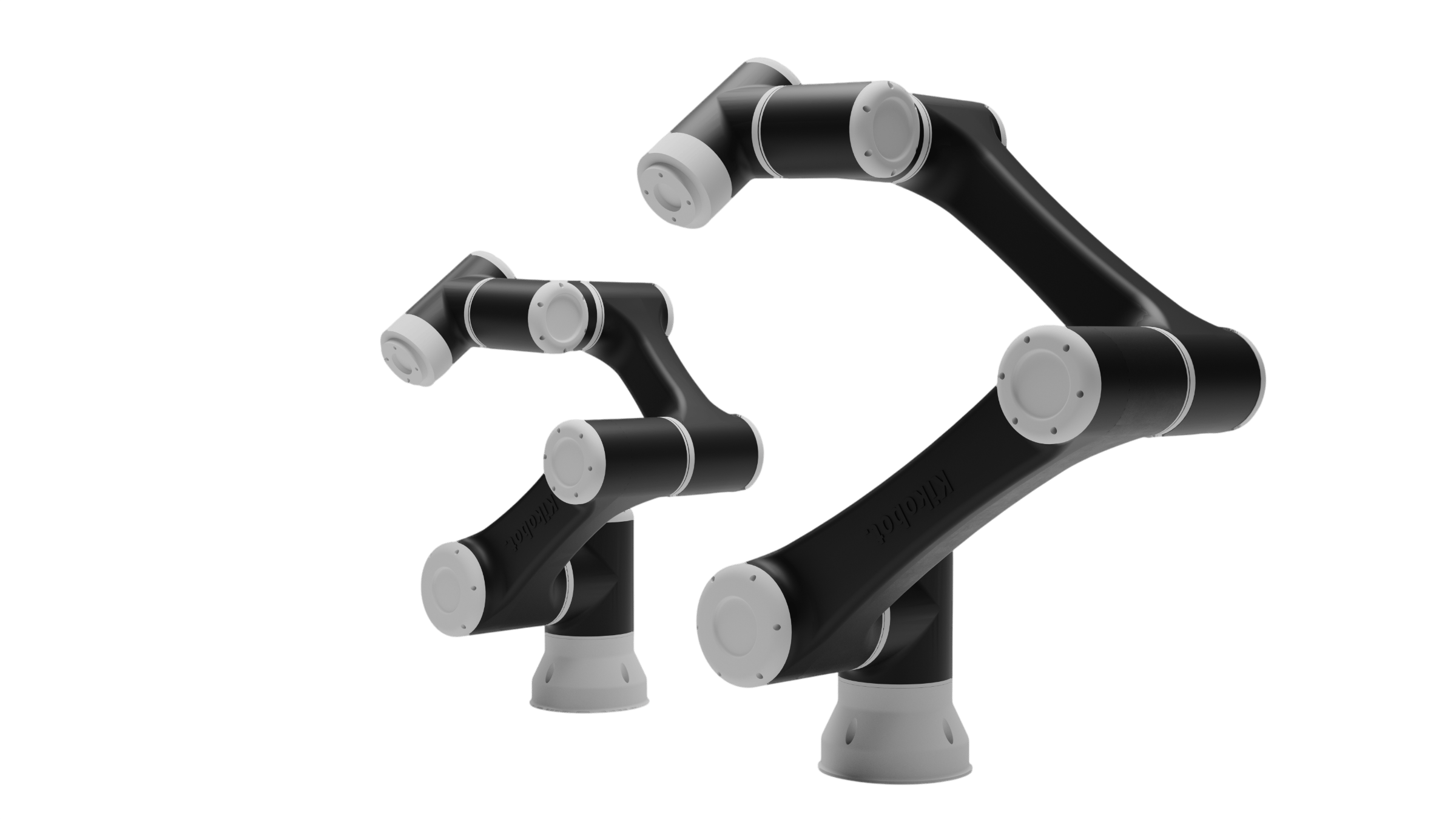
Models and selection
Start with payload and reach, then check the complete tool-and-part mass, centre of gravity, motion path, mounting and required cycle. All four models use six degrees of freedom.
3 kg payload · 600 mm working radius
5 kg payload · 860 mm working radius
7 kg payload · 960 mm working radius
10 kg payload · 1400 mm working radius
Scroll horizontally to view and compare every column.
| PARAMETER | CI3 | CI5 | CI7 | CI10 |
|---|---|---|---|---|
| Maximum payload | 3 kg | 5 kg | 7 kg | 10 kg |
| Working radius | 600 mm | 860 mm | 960 mm | 1400 mm |
| Repeatability | ± 0.05 mm | ± 0.05 mm | ± 0.05 mm | ± 0.05 mm |
| Maximum linear speed | 2.5 m/s | 2.5 m/s | 3 m/s | 2.5 m/s |
| Robot weight | 14 kg | 24 kg | 25 kg | 39 kg |
| Degrees of freedom | 6 | |||
| Range of motion | ± 360° all joints | ± 360° all joints | ± 360° (J3 ± 150°) | ± 360° (J3 ± 150°) |
| Controller I/O | 8 DI · 8 DO | |||
| Communication | Ethernet / Modbus | |||
| End effector I/O | DI, DO, AI, AO · RS485 | |||
| Power supply · rated voltage | 100–240 V AC · 48 V DC | |||
| Nominal power | 400 W | 550 W | 600 W | 750 W |
| Operating temperature | 0–60 °C | |||
| Installation | Floor mounting | |||
| Arm materials | Aluminium · ABS | |||
Every CI robot shares the same controller, the same I/O and the same software — only the arm changes. Values from the CI Series datasheet.
Selection checklist
A model number is only the starting point. These application inputs determine whether the robot, tooling and cell can meet the job.
Part mass, gripper or process-tool mass, centre of gravity and any cable or hose load.
Pick and place points, approach clearances, mounting location, orientation and target cycle time.
PLC, machine, vision, end-effector, I/O, fieldbus, utilities and guarding requirements.
Shift pattern, ambient conditions, materials handled and any cleanliness or process constraints.
Standard platform
Digital I/O, Ethernet and RS485 sit on the controller as standard. Confirm the required gripper, sensor, PLC, vision and safety interfaces for the configured cell.
Opto-isolated digital I/O for grippers, sensors, stack lights and line handshakes.
Modbus TCP and RTU on board, so PLCs, drives and vision talk to the robot directly.
Runs off single-phase mains anywhere in the world. No transformer, no dedicated supply.
Small enough to sit under the bench and light enough to move between cells.
Software
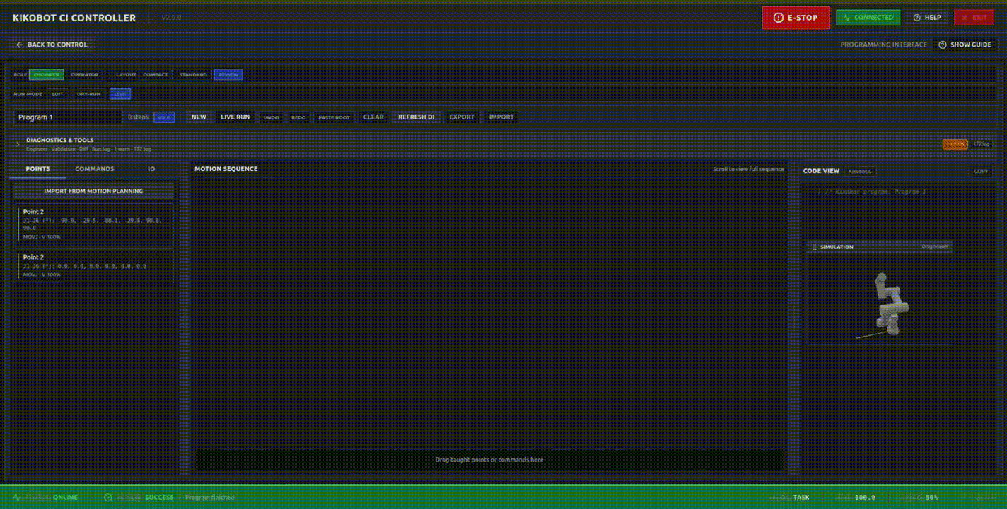
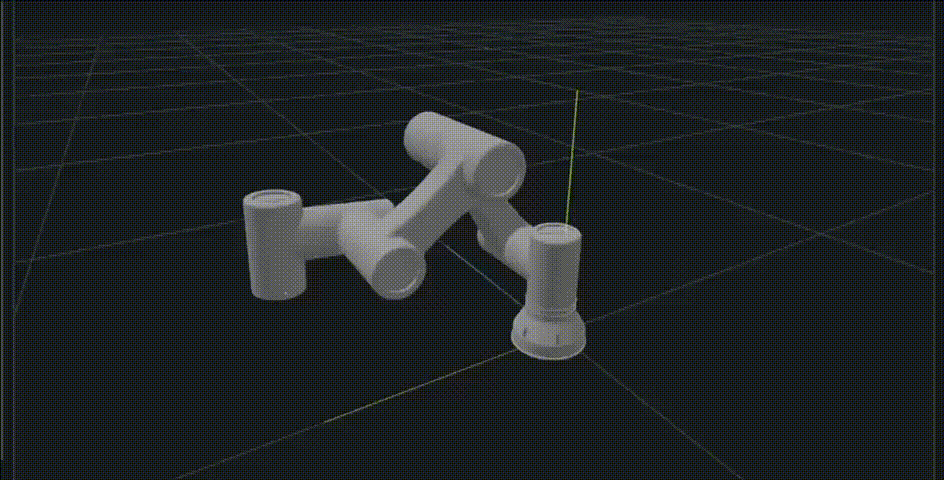
Build a routine with visual blocks, review it in 3D before commanding the robot, and connect configured vision and I/O where the application requires them.
Windows · macOS · Linux · Tablet
Included with every CI robot
GIF — VISION-GUIDED PICKING
Illustrative production view
UNITS TODAY
4,182
+6% vs yesterday
AVG CYCLE
4.2 s
Target 4.5 s
UPTIME
98.6%
Last 30 days
Joint 4 temperature trending up over 300 cycles
Likely cause: payload above rated on the outfeed move. Suggested action: re-check grip offset, or book service inside 12 days.
All other joints within normal range · last calibration 41 days ago
HealthyMachine tending, palletising, dispensing, inspection and packaging start from a working program, not a blank canvas.
One installer for laptop, desktop or tablet. Program at your desk, walk to the cell and carry on where you left off.
Bring available joint, cycle and fault information into one place to support troubleshooting.
Why Kikobot
Every CI model shares the same controller, I/O and software; only the arm changes.
Programming, simulation, I/O, templates and diagnostics sit in the application supplied with each CI robot.
Digital I/O, Ethernet, Modbus and RS485 are available on the standard controller and end-effector interface.
Applications
Configure loading and unloading around the machine interface, part presentation, guarding and required operating pattern.
Move parts between conveyor, tray and fixture, with vision added where the configured presentation and accuracy require it.
Build or break down layers after checking the full load, reach, stack height, cycle and cell layout.
Integrate insertion, seating or fastening tooling with the process controls and records required by the application.
Coordinate a taught path with the selected dispensing equipment and validate bead quality on the real material and process.
Combine handling with a configured inspection step, then validate the decision criteria and packing sequence together.
Before you order
Industrial systems are configured and quoted, not purchased from a generic cart. The proposal is the source of truth for the application and commercial scope.
Selected arm, controller, software, standard and optional equipment, integration responsibilities and exclusions.
The payload, reach, cycle and process assumptions to be checked before order, with acceptance criteria where applicable.
Price, taxes, delivery, commissioning scope, training, warranty terms, support route and spare-parts assumptions.
Published specifications support initial selection. Final suitability, safety, cycle performance and acceptance are established for the configured application before order.
Downloads and quote
Send the part weight, required reach, cycle time and end-effector details. We will use them to discuss the CI model and cell configuration.